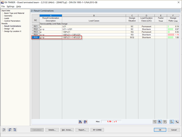
I have a question about the results of the serviceability limit state design: How is the increment of the dead load by the factor of 1.8 and the imposed load by 1.48 explained in the result combinations for the SLS design?
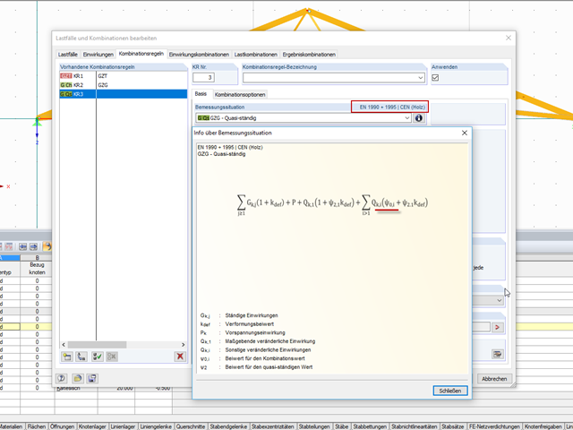
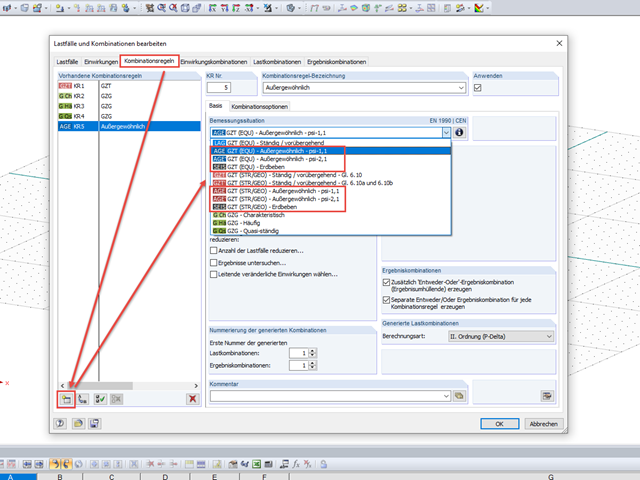
I have created automatic load combinations according to EN 1990 + 1995 (CEN). Although Ψ2,1 = 0, factors greater than zero are applied for wind and snow. Is this a program error?
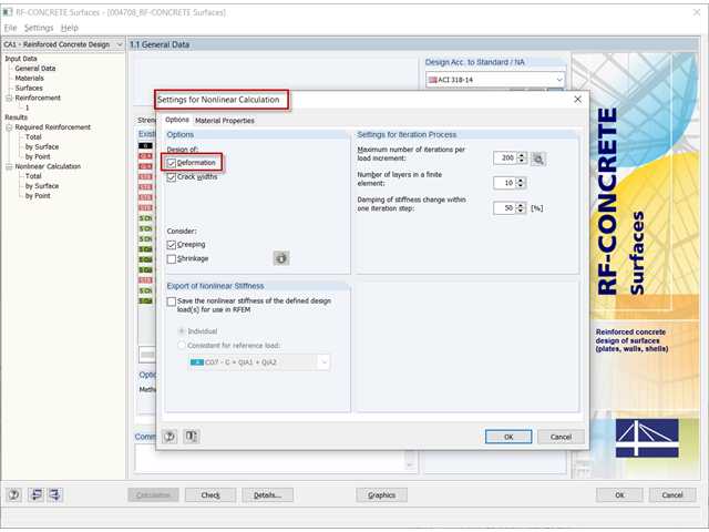
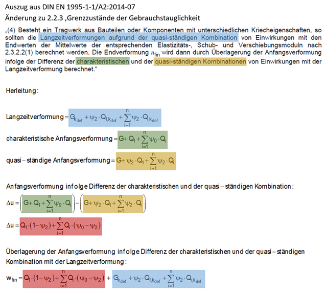
I am designing a combined structure made of timber materials with different creeping parameters. How can I perform the serviceability limit state design according to EN 1995‑1‑1?
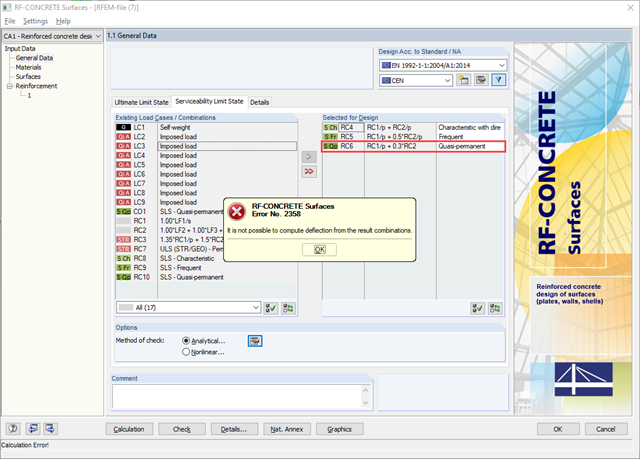
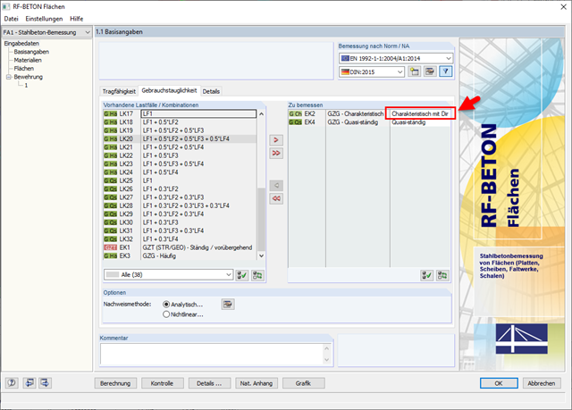
When starting the calculation in RF‑CONCRETE Surfaces, I get the error message "Failed to calculate the deflection for the result combination". Why? What can I do to solve this problem?
In the case of the serviceability limit state design (for example, of a steel beam), the precamber is not taken into account. Is this a program error or is my entry incorrect?
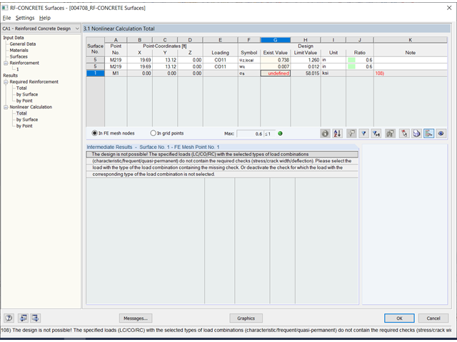
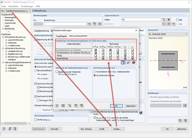
In the RF‑CONCRETE Surfaces add-on module, I get a design failure for the serviceability limit state (SLS) and no values are displayed for the steel stresses. Also, Message 239) is displayed. Why?
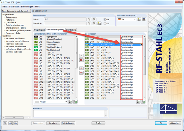
For a steel frame, I have manually created 20 load combinations with partial safety factors. However, the deformations should be determined without the factors. For this, I proceed as follows:
I copy each CO individually (several COs cannot be copied at the same time).
Error message for concrete design: Design is not possible. The specified loading with the selected load combination types does not contain any required design checks.